How to Build: All-in-One PC
1. Prepare the Chassis
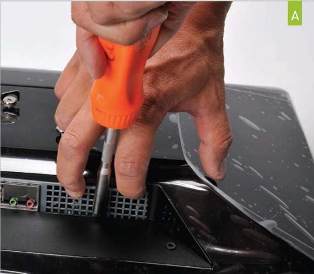
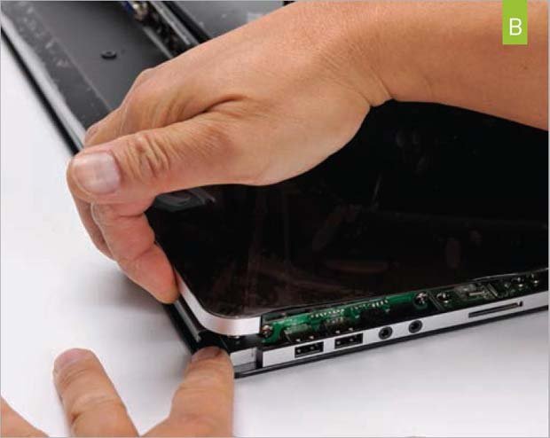
To open the Loop L5, lay it facedown on a clean, nonscratch surface and remove the five screws on back. Now, with the opening for the I/O shield facing you, gently push the tip of your screwdriver on the metal next to the exhaust vent while carefully pulling up on the chassis with your fingers (image A) until the back pops off just a bit. Then, carefully pry off the back, starting at the USB ports and headphone ports (image B) . You’ll use this same process to access the guts of the AiO for future upgrades.
2. Install Drives, CPU and RAM
We’ll skip the usual illustration of mounting the optical drive and SSD/HDD in the caddies and screwing them down, as the process is well known to most Maximum PC readers, but you can go ahead and do this now. (For new builders, Intel provides thorough video instructions for building a system in the Loop here ). Likewise, you’ve seen us install RAM and the CPU dozens of times; now is a good time to do that, as well. With the board out, you should also slot the Wi-Fi card into the Mini PCIe slot nearest the PCIe slot. Then, install the I/O shield.
3. Install the Backplate
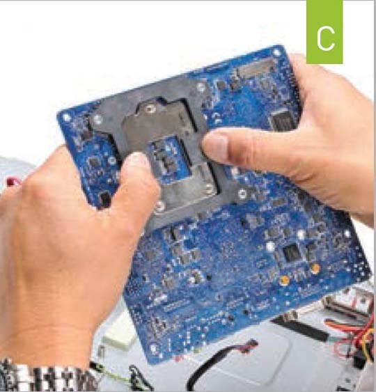
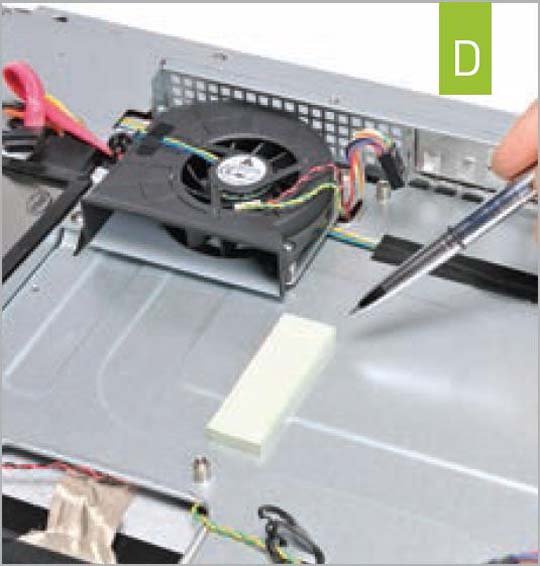
To Use the Stock Intel thermal cooler, you’ll need to install the backplate that comes with the kit. It sticks on with an adhesive pad (image C) . The chassis should also have come with a thick thermal pad that gets mounted to the back of the motherboard, under the voltage regulation modules, or, if you can aim properly, to the chassis itself (image D) . It mounts using an adhesive, so choose wisely. Now, mount the motherboard and screw it in place. As always, pay special attention to how the openings in the I/O shield line up with the motherboard before you screw it down (i.e., make sure the metal fingers coming off the I/O shield don’t jam into the ports.)
4. Install the Cooler
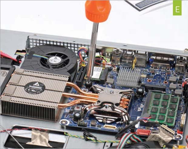
With the Motherboard in place, it’s time to screw the cooler in place. The cooler should have an Intel thermal pad in place. If yours doesn’t, or you are mounting it for a second time, add a small bit of thermal paste to the CPU and spread it out with a plastic bag across the surface of the heat spreader. Use the four screws to mount the cooler to the backplate (image E) , and also screw down the two screws at the end of the heat pipe.
5. Push aside the Speaker
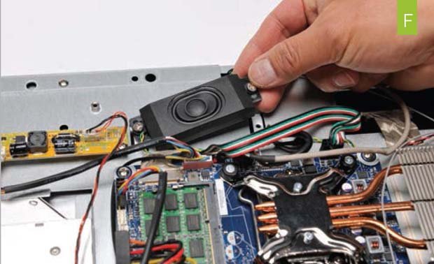
It’s Pretty tight in the AiO, so for removing or installing cables, you’ll have to remove or simply move the speaker on the left side of the machine. Just undo one screw and move the speaker out of the way (image F) .
6. Plug in the Panel
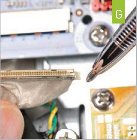
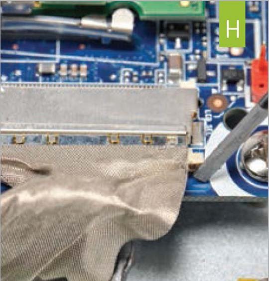
The Panel uses a delicate internal LVDS connector. While at first glance it appears to go in either way, the connector is keyed (image G) . Carefully insert the cable into the LVDS port and then use a small object, such as a flat-head screwdriver, to carefully push it into place by alternatively nudging on each side of the connector while holding one side with your finger (image H) . Once it’s in place, don’t ever remove the LVDS connector by tugging on the ribbon cable. If you have to remove it, use a small flat-head screwdriver to slowly nudge it out from the sides.
Click the next page to learn how to plug in the audio, wifi, and for the final stages.
Keep up to date with the most important stories and the best deals, as picked by the PC Gamer team.
