How to Build a Modern Commodore 64 PC
3. INSTALL THE OPTICAL DRIVE
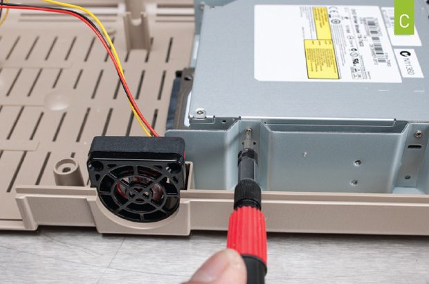
We couldn’t find a 170KB 5.25-inch floppy drive, so we settled for this Silverstone slot-fed DVD burner. It comes with four tiny screws. Place the drive in the cage and screw it in place with the jeweler’s screwdriver (image C) . Now plug in the HDD power and SATA cable as well as the ODD power and data cable.
4. INSTALL THE ALL-IN-ONE MOTHERBOARD
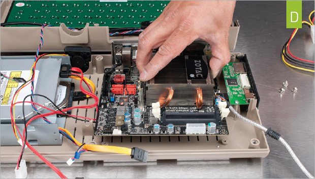
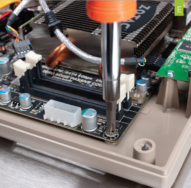
Install the I/O shield by sliding it into the slots at the rear of the C64x. Now gently slide the Zotac motherboard into place, making sure the two Wi-Fi antennas feed out the holes in the I/O shield (image D) . Take four screws from your spare parts box (because why would Commodore USA bother to include them in the box?) and gently screw the board in place (image E) . The board doesn’t have metal standoffs, so you’ll be boring the screws into plastic. Do not over-torque the screws or you will strip out the mounts.
5. INSTALL THE RAM
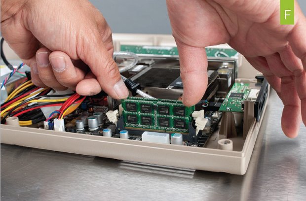
Install the pair of SODIMMs by placing them into the slots while carefully making sure the notches in the DIMMs line up with the notches in the slots. Apply pressure with your thumbs on the corners until the arms snap into place (image F) .
6. EXPANSION NEEDED
Keep up to date with the most important stories and the best deals, as picked by the PC Gamer team.
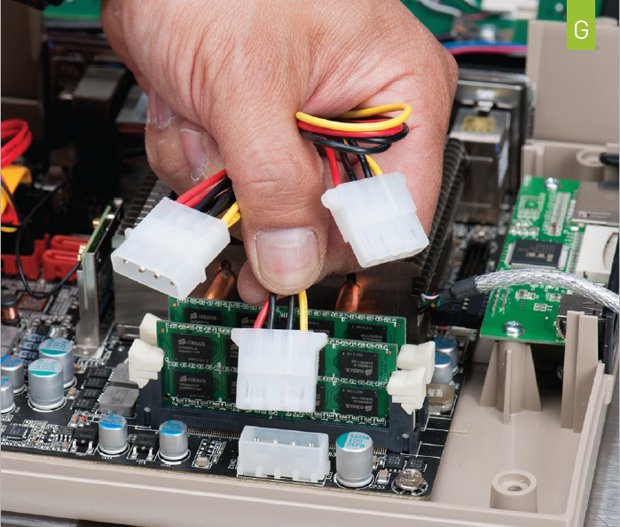
Since the keyboard is internal, it hooks directly into a USB 2.0 header. Unfortunately, the system’s internal media card reader also requires a USB 2.0 header, but the Zotac board we selected has only one internal USB 2.0 header and a USB 3.0 header. To get around this, we used an NZXT 1U01 USB expansion module. The 1U01 needs power, so take the Molex Y-cable splitter and plug it into the Molex output on the motherboard (image G) . Now take the Molex-to-SATA power connector that came with the motherboard and plug it into one end of the Y-cable splitter. Plug the other end into the 1U01’s power pass-through and then plug into the optical drive’s Molex cable.
7. HOOK UP THE KEYBOARD
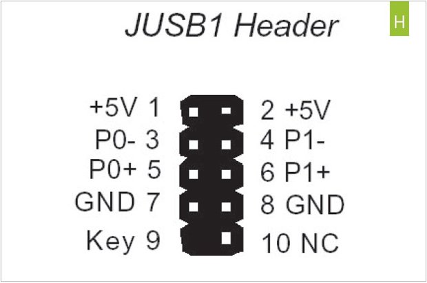
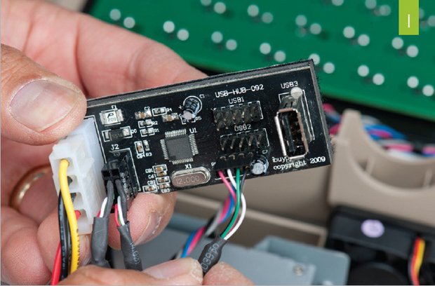
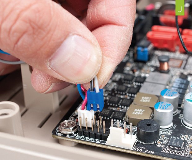
The USB cable isn’t labeled, but the wires indicate what functions they do. The red wire is power and the black is ground. Look at the USB pin-out chart we’ve provided (image H) and match the keyboard connector that has the red wire with one of the +5V pins and then plug it in (image I) . If you’re still skittish, you can grab one of those USB header adapters that ship with MSI and Asus boards. Plug the power switch and power LED into the board’s front-panel connectors (image J) .
Alan has been writing about PC tech since before 3D graphics cards existed, and still vividly recalls having to fight with MS-DOS just to get games to load. He fondly remembers the killer combo of a Matrox Millenium and 3dfx Voodoo, and seeing Lara Croft in 3D for the first time. He's very glad hardware has advanced as much as it has though, and is particularly happy when putting the latest M.2 NVMe SSDs, AMD processors, and laptops through their paces. He has a long-lasting Magic: The Gathering obsession but limits this to MTG Arena these days.

