A new generation of video encoders is upon us! Some sound familiar, such as H.265, some sound exotic and new, like VP9 or AV1, but no matter what, you’ll likely be tripping over one or the other soon, and cursing that your CPU use has shot through the roof.
Why do we need a raft of new encoders? Why has your hardware acceleration stopped working? Is that 4K file going to play on your 4K UHDTV? What about HDR on the PC? How can you encode your own video, and can you even enjoy some GPGPU acceleration, too? Can we make it all simple for your perplexed brain?
We’re going to take a deep dive into the inner workings of video encoders to see how gigabytes of data can be compressed to 1/100 the size and the human eye can’t tell the difference. It’s going to be like the math degree you never got around to taking at community college, but probably a lot more useful!
If you want to control your encodes better, it really does help to have an understanding of what’s going on inside the encoder. Ironically, none of the standards mentioned above defines the encoder, just what’s required for the decoder. As we’ll see, this does enable the encoder writer to use all manner of techniques and user settings to enhance encodes, usually at the expense of longer encode times and more processor usage, for either a smaller file or enhanced quality.
Once upon a time, there were animated GIFs, and boy those things were terrible. You can see the problem: People want to store moving images on their computers, and a fixed 256-color palette standard that stored full frames was not the future; this was back in 1987.
What we’ve had since then is 30 years of steady encoding enhancements from a well-organized international standards committee. Well, up until the last decade, but we’ll come to that.
We’re not going to dwell on the history, but it’s worth noting a couple of things that have fixed naming conventions and systems in place. Before moving images, there were still images. The first working JPEG code was released at the end of 1991, and the standard in 1992, out of the work by the Joint Photographic Experts Group, which started working on JPEG in 1986.
Keep up to date with the most important stories and the best deals, as picked by the PC Gamer team.
Similarly, the International Telecommunications Union (ITU) formed the Video Coding Expert Group (VCEG) way back in 1984 to develop an international digital video standard for teleconferencing. That first standard was H.261, finalized in 1990, and designed for sending moving images at a heady 176x144 resolution over 64kb/s ISDN links. From this, H.262, H.263, H.264, and H.265 were all born, and after H.261, the next video standard worked on was known as MPEG-1.
So, you can see where these standards came from. We’ve mentioned JPEG for two reasons: First, MPEG (Moving Picture Experts Group) was formed after the success of JPEG. It also used some of the same techniques to reduce encoded file size, which was a huge shift from existing lossless digital storage to using lossy techniques.
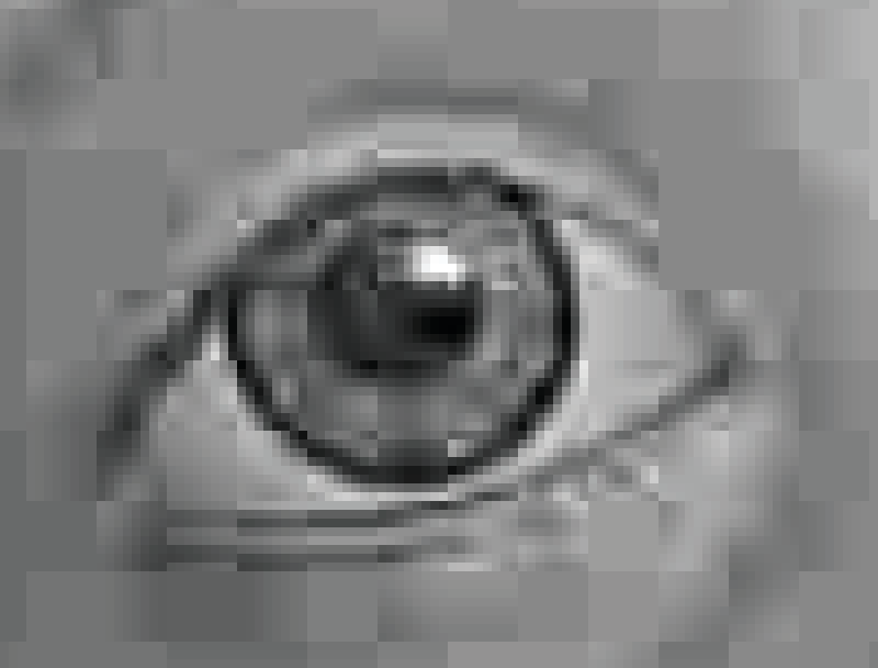
One of the most important things to understand about modern lossy compression is how the image is handled and compressed. We’re going to start with the basics, and how JPEG compression (see image above) works—it’s at the heart of the whole industry—and expand that knowledge into motion pictures and MPEG. Once we’ve got that under our belt, we’ll see how these were improved and expanded to create the H.264 and H.265 standards we have today.
Space: the colorful frontier
The first thing to get your head around is the change in color space. You’re probably used to thinking of everything on PCs stored in 16-, 24-, or 32-bit color, spread over the red, green, and blue channels. This puts equal emphasis on storing all color, hue, and brightness information. The fact is, the human eye is far more sensitive to brightness, aka luminance, than anything else, then hue, and finally color saturation.
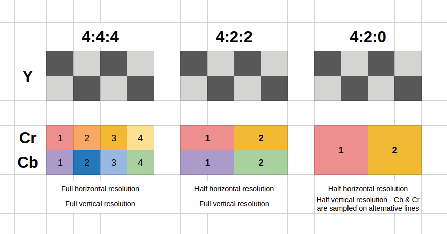
The color space is changed from RGB to YCbCr, aka luminance and two chrominance channels (blues and reds here)—if you’re wondering, this is related to YUV. The reason is to enable chroma subsampling of the image; that is, we’re going to reduce the resolution of the Cb and Cr channels to save space (hopefully) without any perceivable drop in quality.
This is expressed as a ratio of the luminance to the chroma channels. The highest quality—full RGB—would be 4:4:4, with every pixel having Y, Cb, and Cr data. It’s only used in high-end video equipment. The widely used 4:2:2 has Y for every pixel, but halves the horizontal resolution for chroma data; this is used on most video hardware. 4:2:0 keeps horizontal resolution halved, but now skips every other vertical line (see image above)—this is the encoding used in MPEG, every H.26x standard, DVD/Blu-ray, and more. The reason? It halves the bandwidth required.
The science bit
Now the heavy math kicks in, so prepare your gray matter…. For each channel Y, Cb, and Cr, the image is split into 8x8 pixel blocks. With video, these are called macroblocks. Each block is processed with a forward discrete cosine transform (DCT)—of the type two, in fact. “What the heck is that?” we hear you ask. We unleashed our tamed Maximum PC mathematician from his box, who said it was pretty simple. Well, he would! Then he scurried off, and installed Arch Linux on all our PCs. Gah!
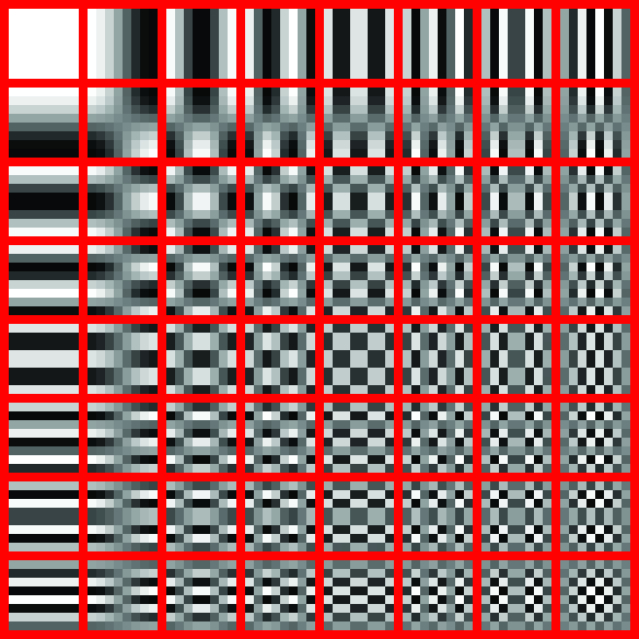
The DCT process transforms the discrete spatial domain pixels into a frequency domain representation. But of what? Take a look at the 8x8 cosine grid—the black and white interference-like patterns (see image above). The DCT spits out an 8x8 matrix of numbers; each number represents how much like the original 8x8 image block is to each corresponding basis function element. Combine them with the weighting specified, and you get a close enough match to the original that the human eye can’t tell the difference.
As you’ll spot, the top-left basis function element is plain (described as low frequency), and will describe the overall intensity of the 8x8 grid. The progressively higher frequency elements play less and less of a role describing the overall pattern. The idea being we’re able to ultimately drop much of the high-frequency data (the details parts) without loss of perceived quality.
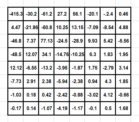
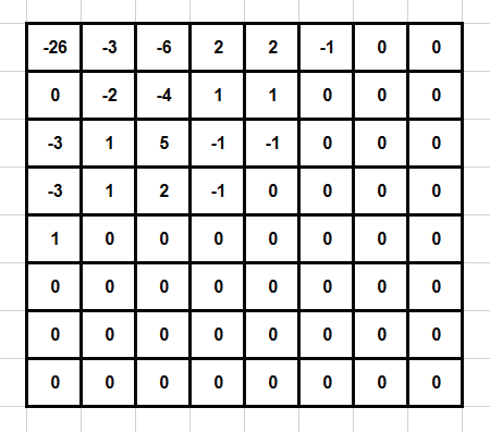
This DCT matrix is run through a 8x8 quantizer matrix; standard matrices are provided (based on researched amounts), but software encoders can create their own for, say, 50 percent quality, as it goes along. The quantizer is devised to try to retain low-frequency detail—which the eye sees more easily—over high-frequency detail. Each DCT element is divided by each corresponding quantizer element, and the result rounded to the nearest integer. The end result is a matrix with low-frequency elements remaining in the top-left of the matrix, and more of the high-frequency elements reduced to zero toward the bottom-right of the matrix, which is where the lossless element of JPEG comes in.
Due to this top-left weighting, the matrix is rearranged into a list using a “zig-zag” pattern, processing the matrix in diagonals, starting top-left, which pushes most zeros to the end (see images above). Huffman Encoding compresses this final data. Quality of the JPEG image is controlled by how aggressive the quantizer matrix is. The more strongly it attempts to round down elements to zero, the more artifacts. Congratulations—you’ve compressed a still image!
If JPEG is so good at compressing, why not stick a load together to make a moving image format? Well, you can—it’s called Motion JPEG—but it’s hugely inefficient compared to the moving picture encoding schemes.
Motion compression
For MPEG (and other compression schemes), each frame is split into macroblocks of 16x16 pixels. Why not the 8x8 that is used by JPEG and used within the MPEG standard? Well, MPEG uses 4:2:0 color space, which skips every horizontal line, so we need to double up to retain an even amount of data horizontally and vertically.
The MPEG standard uses three types of frame to create a moving image. I (intra) frames are effectively a full-frame JPEG image. P (predicted) frames store only the difference between an I-frame and the future P-frame. In between these is a series of B (bidirectional or inter) frames, which store motion vector details for each macroblock—B-frames are able to reference frames before and upcoming.
So, what’s happening with motion vectors and the macroblocks? The encoder compares the current frame’s macroblock with adjacent parts of the video from the anchor frame, which can be an I or P frame. This is up to a predefined radius of the macroblock. If a match is found, the motion vector—direction and distance data—is stored in the B-frame. The decoding of this is called motion compensation, aka MC.
However, the prediction won’t match exactly with the actual frame, so prediction error data is also stored. The larger the error, the more data has to be stored, so an efficient encoder must perform good motion estimation, aka ME.
Because most macroblocks in the same frame have the same or similar motion vectors, these can be compressed well. In MPEG-1, P-frames store one motion vector per macroblock; B-frames are able to have two—one from the previous frame, and one from the future frame. The encoder packs groups of I, P, and B frames together out of order, and the decoder rebuilds the video in order from these out of the MPEG bitstream. As you can imagine, there’s scope for the encoder to implement a wide range of quality and efficiency variables, from the ratio of I, P, and B frames to its motion compensation efficiency.
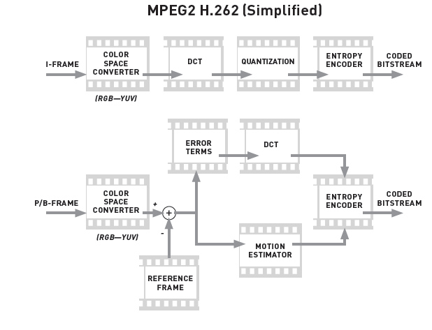
At this point, we’ve covered the basics of a compressed MPEG-1 video. Audio is integrated into the bitstream, and MPEG-1 supports stereo MP3 audio, but we’re not going to go into the audio compression. MPEG-2 (aka H.262, see image above) uses largely the same system, but was enhanced to support a wider range of profiles, including DVD, interlaced video, higher-quality color spaces up to 4:4:4, and multi-channel audio. MPEG-3 was rolled into MPEG-2 with the inclusion of 1080p HD profiles.
