Ultimate BIOS Guide: Every Setting Decrypted and Explained!
Advanced CPU Features
Gigabyte's latest boards clumps these entries together in a handy submenu, but depending on your make and model, you may find these settings spread out in different sections of your BIOS.
CPU Clock Ratio: Otherwise known as the multipler, this number multiplied by your CPU's base frequency determines your processors clockspeed. See chipset-specific BIOS options below.
Intel Turbo Boost Tech.: New to Nehalem (Core i7), enabling this feature will temporarily boost processor cores to run faster than their stock frequency depending on the current power, current, and temperature levels.
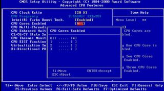
CPU Cores Enabled: Allows you to enable all or just some of your processor's cores.
CPU Multi-Threading: Enable this option to take advantage of Intel's HyperThreading technology.
CPU Enhanced Halt (C1E) : A power saving feature in Intel chips, enabling C1E will allow the operating system to send a halt command to the CPU when inactive. This halt state reduces both the processor's voltage and multiplier so that it consumes less power and runs cooler. This doesn't affect performance, though some power users have noted better overclocking headroom when disabling this setting.
C3/C67/C7 State Support: Essentially a revised version of C1E, these higher-numbered halt states put the processor into an even lower power state when idle. Again, overclocking results may vary, but performance does not.
PC Gamer Newsletter
Sign up to get the best content of the week, and great gaming deals, as picked by the editors.
CPU Thermal Monitor: First introduced with the Pentium 4, current iterations take a somewhat different approach by dropping down the core clockspeed and voltage when things get a bit too hot under the collar.
CPU EIST Function: Short for Enhanced Intel SpeedStep, this power-saving setting allows Intel chips to dynamically change frequency and voltage levels in small increments based on need.
Virtualization Technology: Enabling this feature allows virtualization programs like VMWare and Virtual PC to tap into your processor's hardware virtualization support
Bi-Directional PROCHOT: Enabling this setting sends a bi-directional signal that indicates if the processor has exceeded its maximum temperature and whether or not it should activate the Thermal Control Circuit (TCC).
PnP/PCI Configurations
This is the section of the BIOS that deals with the PCI bus and Plug-and-Play settings, most notably IRQ mapping. Unless you're attempting to run legacy hardware or are running into troubleshooting issues with your PCI peripherals, you won't be spending much time, if any, in this section.
PCI1 and PCI2 IRQ Assignment: This lets you configure whether to let your PC dole out IRQ resources automatically or to let you configure them manually. Unless you're dealing with older hardware or niggling IRQ conflicts that are not resolved by moving PCI cards to a different PCI slot, you should leave this one on Auto.
PC Health Status
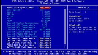
On most Asus boards, this section will come labeled as a Hardware Monitor submenu in the Power section. MSI boards usually call this H/W Monitor accessible through the BIOS's main menu. In each case, this is where you'll find system vitals, such as current system and CPU temperatures, fan speeds, and various voltage levels. This is helpful when troubleshooting overheating issues or power issues, such as random reboots, but treat this as a starting point before digging deeper. Overheating due to a poorly installed heatsink, for example, might not manifest itself until you boot into Windows and encode a DVD or otherwise stress your CPU.
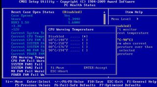
Recent Case Open Status: Only of use with compatible cases, this security feature can detect if your case has been opened and reset the status at the next boot.
CPU Warning Temperature: Sounds an alarm when a certain CPU temperature threshold is reached.
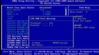
CPU Fan Fail Warning: Sounds an alarm should the CPU heatsink's fan stop spinning, or whichever fan you have plugged into your motherboard's CPU fan power header.
System Fan 2 Fail Warning: Sounds an alarm when the fan plugged into this header stops spinning.
Power Fan Fail Warning: Sounds an alarm when the fan plugged into this header stops spinning (seeing a pattern yet?).
System Fan 1 Fail Warning: Sounds an alarm when...you get the idea.
CPU Smart Fan Control: Disabling this setting allows the CPU heatsink's fan to run at full bore all the time. Enabling this setting will vary the fan speed depending on CPU temperature.
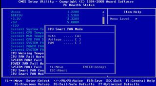
CPU Smart Fan Mode: If you enable CPU Smart Fan Control, you can then set the mode to Auto (controlled by the BIOS), Voltage (for use with 3-pin fans), or PWM (for use with 4-pin fans).
DRAM Timing
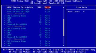
If your motherboard allows you to manually tweak your RAM's latency timings, you'll find them in the overclocking section. These will most often be labeled as MB Intelligent Tweaker (Gigabyte), Cell Menu (MSI), Advanced Chipset (Asus), or Genie BIOS Setting (DFI). Other overclocking options will also be available, but we'll focus on these in more detail later on.
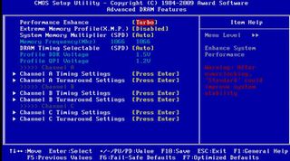
Performance Enhance: Applicable to Gigabyte boards, this section tells the BIOS how aggressively to auto-tune your RAM's settings.
Extreme Memory Profile (X.M.P.): Short for eXtreme Memory Profile, X.M.P.-compatible RAM contain additional, pre-programmed settings tuned for both performance and overclocking.
System Memory Multiplier: Left on Auto, your BIOS will determine the safest multiplier, or FSB:DRAM ratio, and resulting memory frequency for your RAM based on its pre-programmed SPD settings. If overclocking or tuning for additional performance, you can manually set the multiplier.
DRAM Timing Selectable: You may see the letters SPD in this section. This stands for Serial Presence Detect and refers to the information programmed into your memory modules by the manufacturer, which tells the BIOS what latencies and voltage to use at any given clockspeed to ensure compatibility. If left on Auto, your RAM will run at its pre-programmed SPD settings when overclocking. Otherwise, you can change this to Manual (or disabled) to and set your own latency timings.
Channel A/B/C Timing Settings: Refers to your RAM's timings or latencies, separated by memory channel.
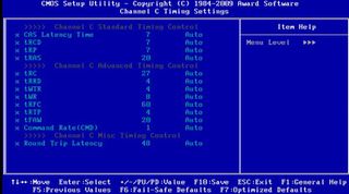
CAS Latency Time: Short for Column Address Strobe, this number dictates the number of clock cycles that pass before data can be read or written to from where it's stored in a column address. The lower the number, the faster this takes place. When shopping for memory modules, the CAS latency is typically the first of a set of four numbers (for example, 8 -8-8-24).
tRCD: Also referred to as DRAM RAS# to CAS# Delay, this number represents the delay in clock cycles it takes to find the fow of a location in memory and finding the column. The lower the number, faster this takes place. When shopping for memory modules, RAS# to CAS# is typically the second number in a set of four (for example, 8- 8 -8-24).
tRP: Also referred to DRAM RAS# Precharge, the RAS precharge is how long it takes for the memory to stop accessing one row, build up a charge, and access another. The lower the number, the fast this takes place. When shopping for memory modules, RAS# Precharge is typically the third number in a set of four (for example, 8-8- 8 -24).
tRAS: Also referred to as Precharge Delay, this number represents the minimum number of cylces that pass between an active and precharge command. The lower the number, the faster the performance. When shopping for memory modules, the Precharge Delay is typically the last (and highest) number in a set of four (for example, 8-8-8- 24 ).
Command Rate (CMD): The Command Rate is the delay, in clock cycles, from when a memory chip is selected to when the first active command can be sent. A 1T command rate offers better performance than 2T, but if you experience instability, you'll want to change this 2T.
Advanced Timing Control: Depending on your motherboard, you may find anywhere from a handful to a boatload of additional RAM timings. These refer to various other dealys and can be overwhelming to even experienced overclockers. Unless you're shooting for a record overclock or trying to get over a certain MHz bump, we recommend leaving these settings on Auto.
Channel A/B/C Turnaround Settings: These submenus control the read and write delay settings, again separated by channel.
Most Popular


